|
|
|
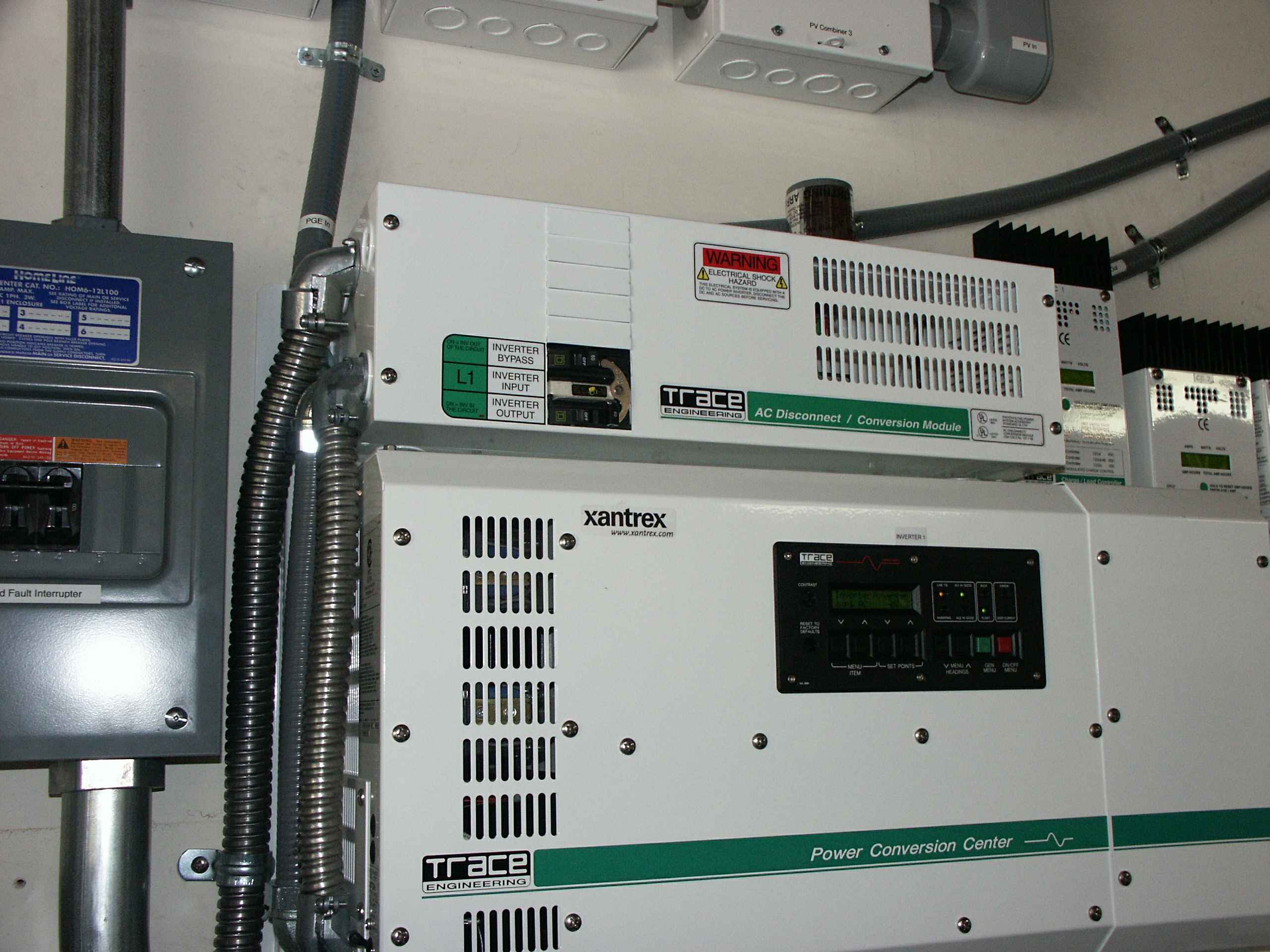
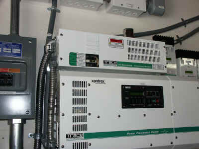
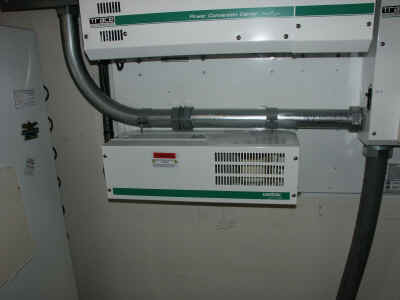
This shows the AC bypass switch mounted above the inverter. If you
look carefully you can see the conduit that contains the main input
feed. If goes into the bypass switch and then through the GTI and
into the inverter's main input. The left-hand silver flex-conduit is the
connection to/from the GTI. The right-hand silver flex-conduit connects the
bypass switch to the inverter's input and output.
Coming out of the bypass switch the power goes out of the top of the
two gray flex cables going diagonally out of the picture.
|
|
|
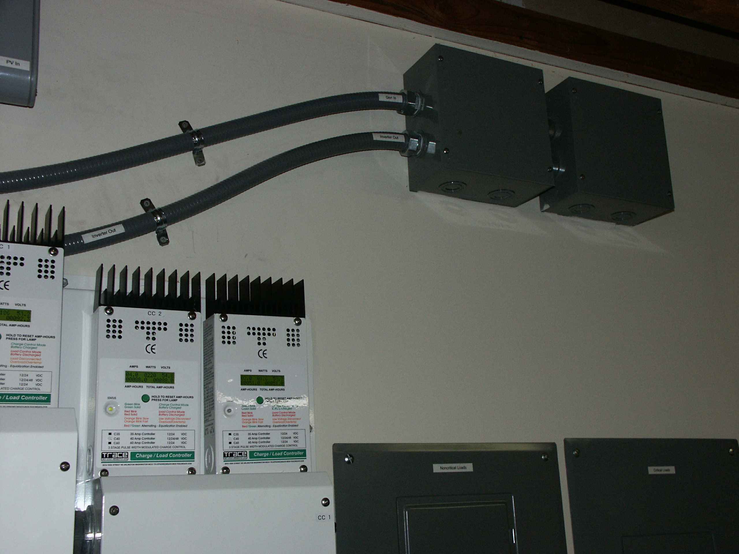
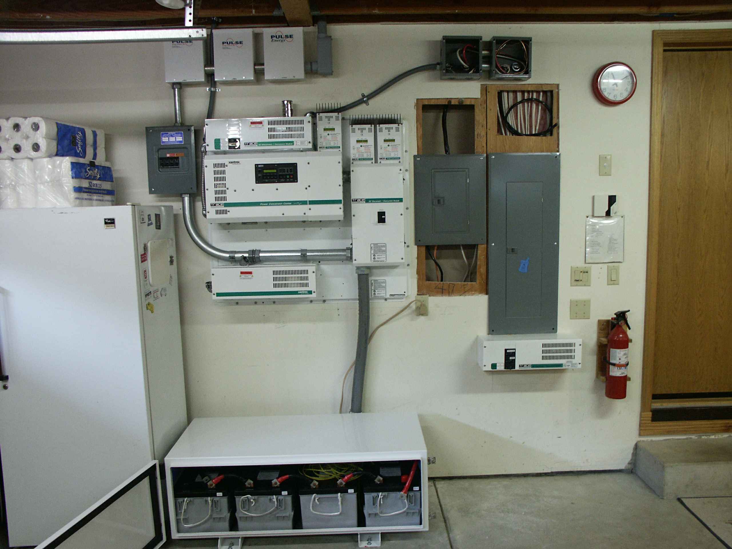
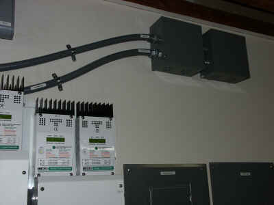
The top flex-conduit carries the AC out of the inverter to the two boxes I
installed to get the wires into the sheetrock. Inside the right-hand
box the cable enters the sheetrock and connects to the right-hand breaker
panel (the critical panel). The main feed that was feeding the house
before comes into the right box and crosses over into the left box to get
into the sheetrock to feed the left-hand breaker panel (non-critical
panel).
The lower flex conduit carries the power from the generator balancing
transformer to the second input of the inverter.
|
|
|
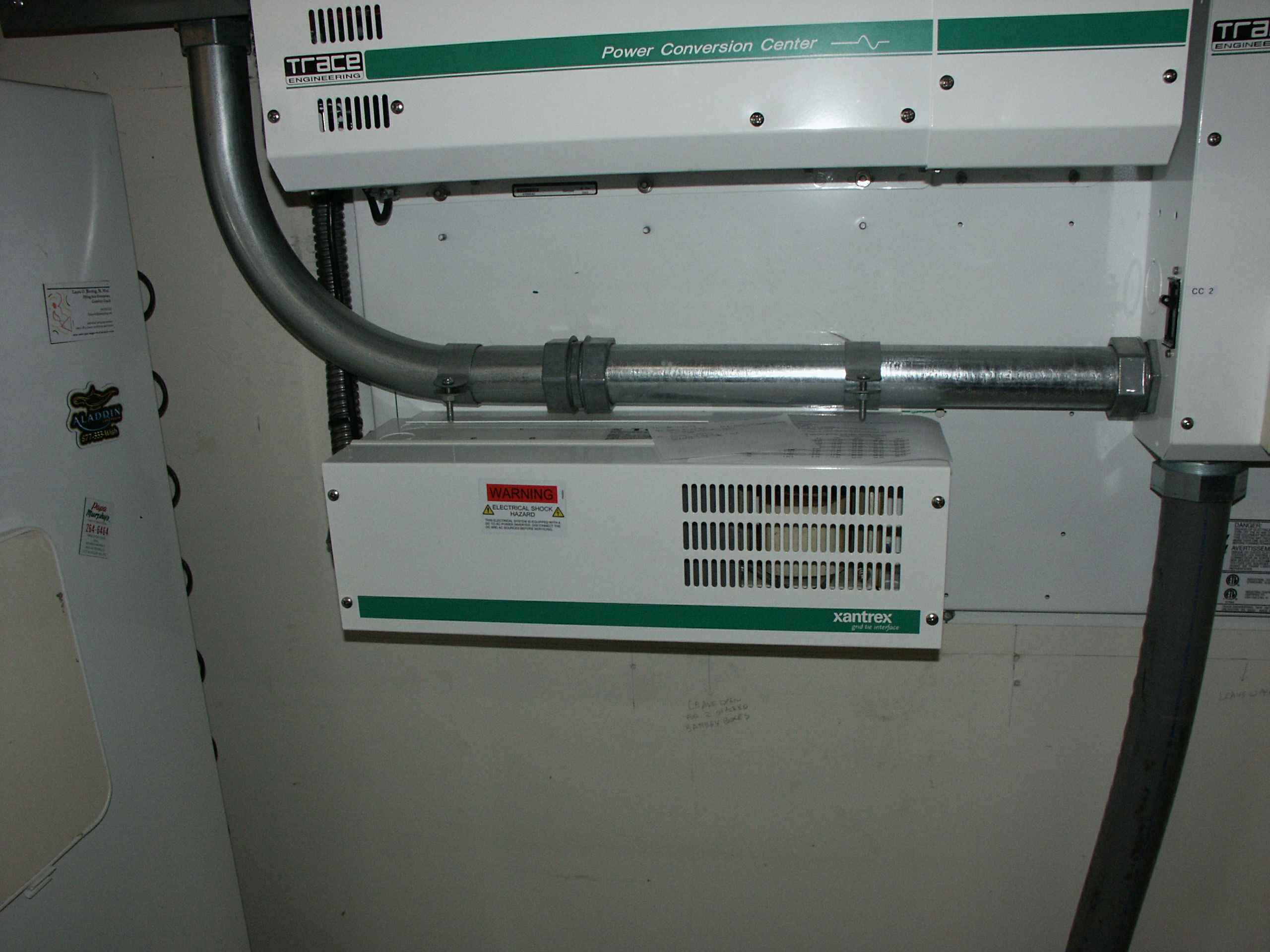
This is the Grid Tie Interface (GTI) that connects the grid to the
inverters output, and bypasses the inverter when it is not selling.
The big pipe above the GTI is the conduit carrying the 3 pairs of #0
wire from the PVGFP to the DC disconnect box. See the DC
Power Path page for more details.
|
|
|
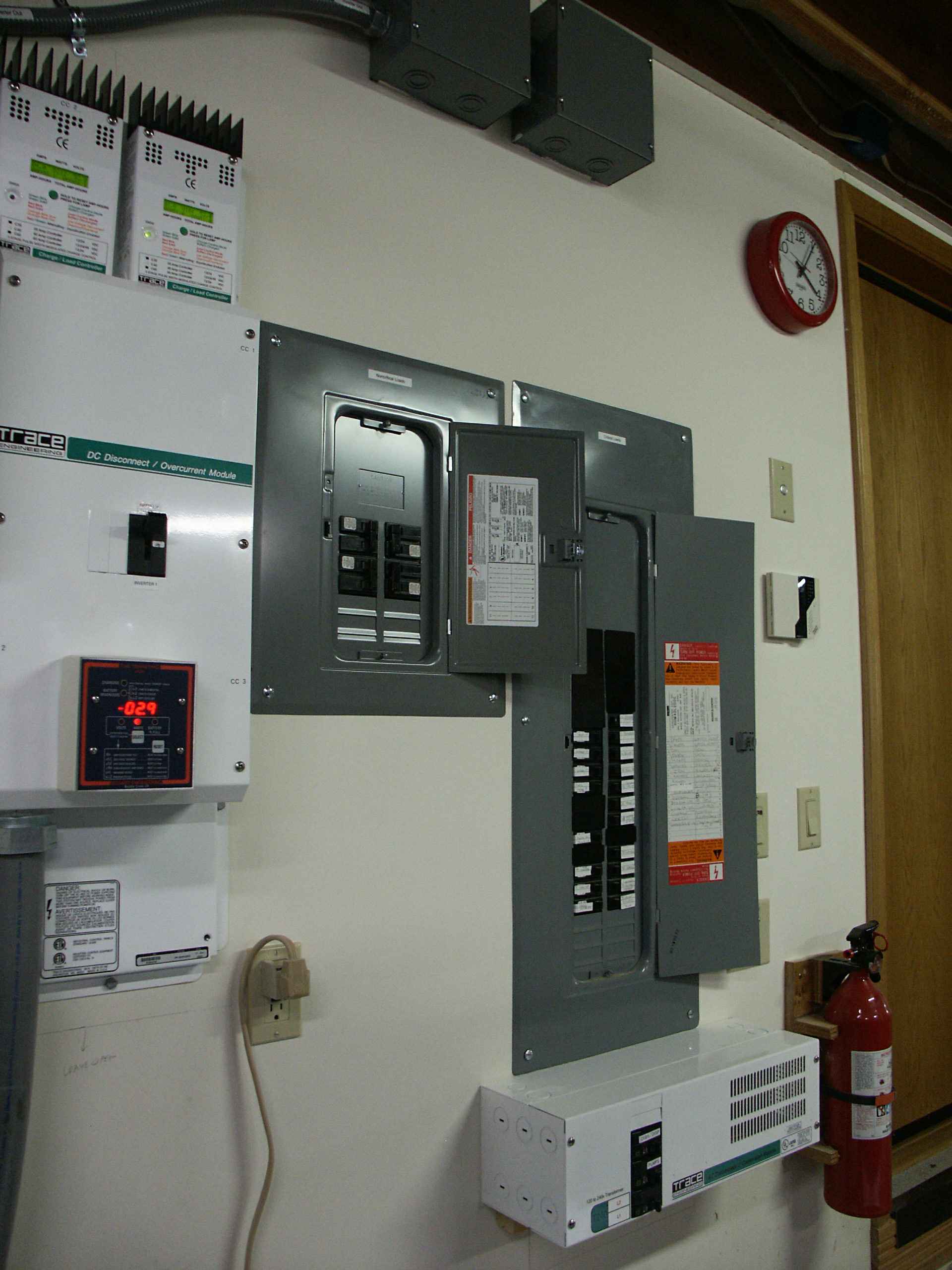
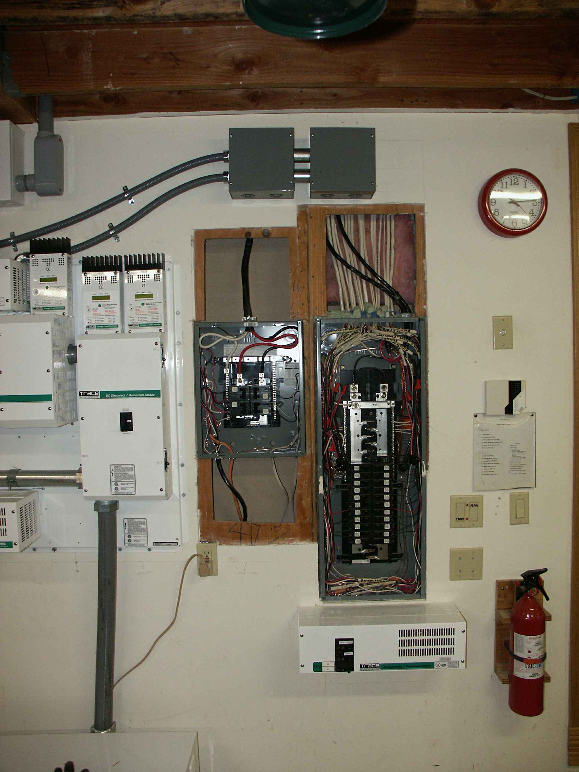
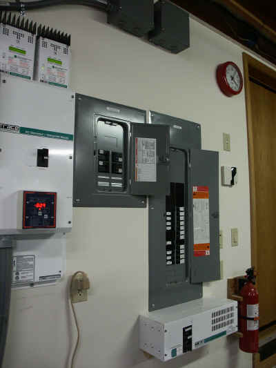
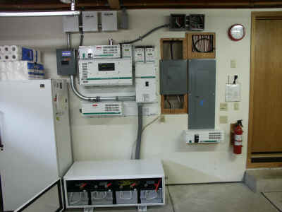
Here you can see both the critical (right) and non-critical (left)
panels. Below the critical panel is the T240 autotransformer that
turns the 120 volts from the inverter to 240 to feed the well pumps.
The critical panel is the one that came with the house. In order
to not overload the inverter I moved four loads to a new panel, the
non-critical panel. This panel is fed directly from PG&E (by the
same wires that originally fed the original panel). I moved the
oven, dryer and two baseboard heater breakers to the non-critical panel
and ran wires from the ends of the original cables to the new panel.
To see a listing of the loads in the Critical Panel click
here.
To see a listing of the loads in the Non-Critical Panel click
here.
|
|
|
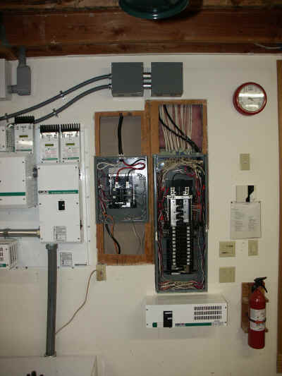
In this picture you can see both panels before I closed up the wall and
put the covers on.
|

|
|
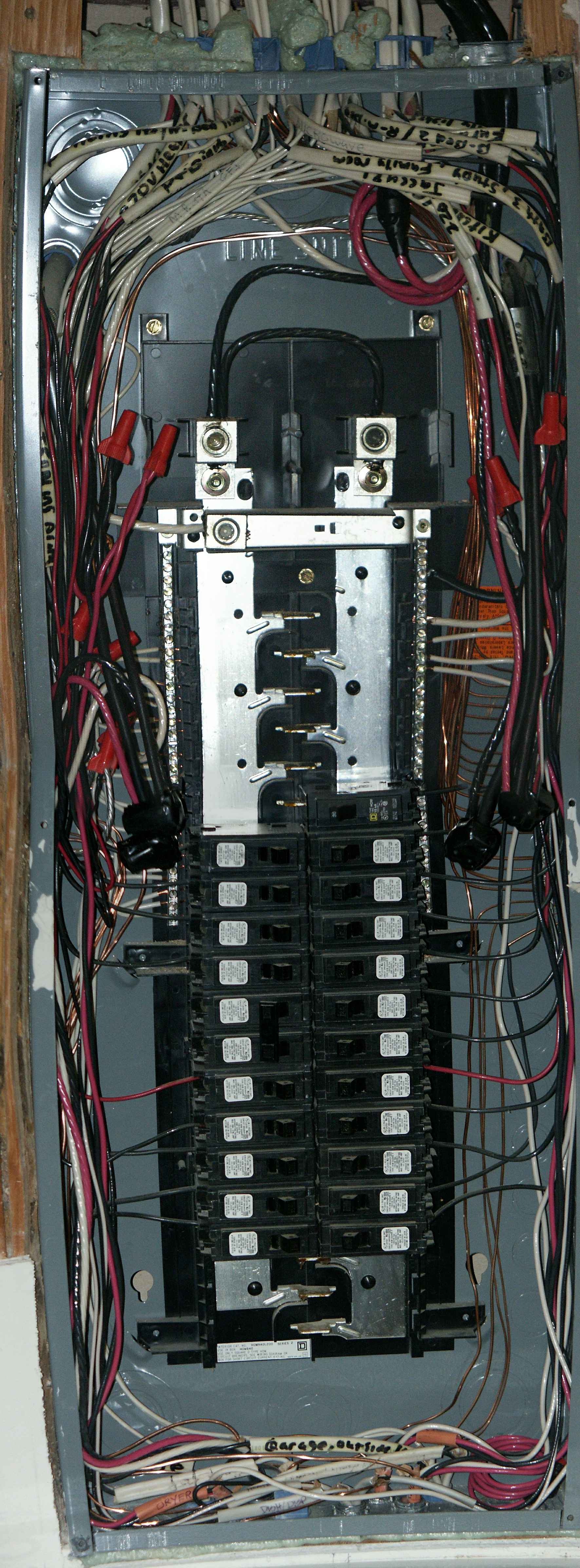
In this close up of the critical breaker panel you can see the connections
I made from the existing wiring to the new wires that go over to the new
non-critical panel.
Also you can see that the two phases of the panel are connected
together with a jumper and fed with one wire coming from the inverter
(through the bypass switch).
|
 |
| This is what it looked like before I closed up the
walls after installing the non-critical breaker panel (the left one) and
rewiring the critical breaker panel.
|