|
|
|
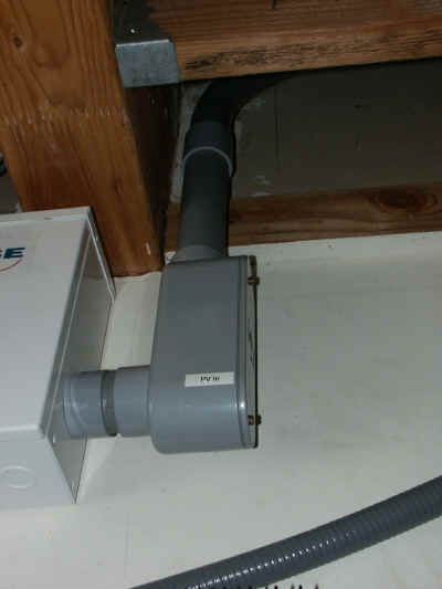
This shows the conduit that houses the 13 pairs of #10 wires from the PV
arrays. It comes into the garage attic from the house attic and
feeds into the combiner boxes.
|
|
|
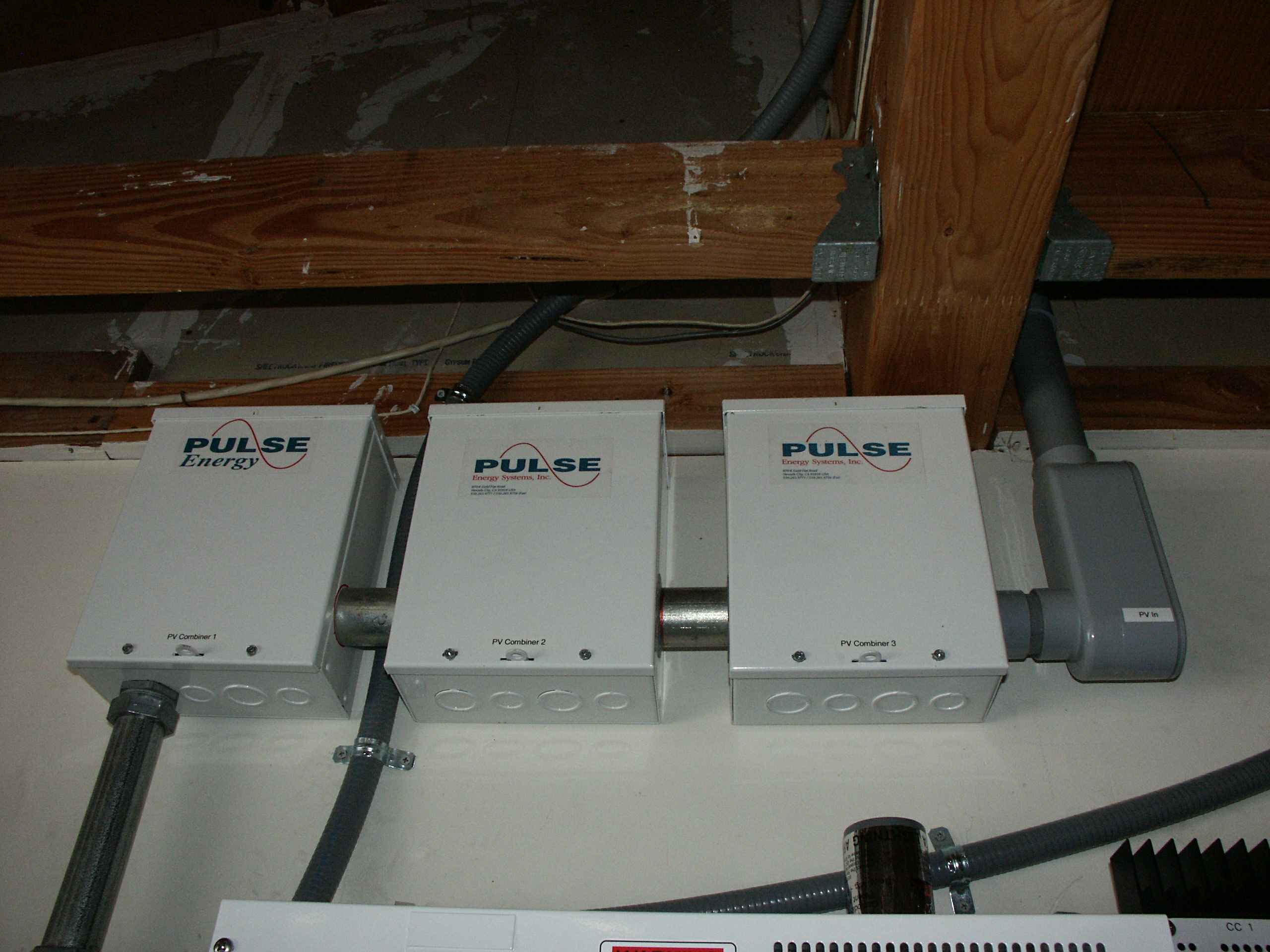
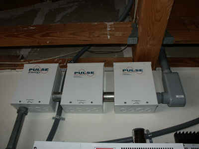
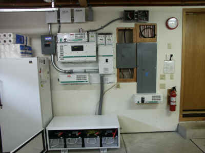
These are the three combiner boxes that combine the 13 PV arrays into 3
circuits. The left and center combiner boxes each combine 4 arrays
and the right one combines 5. The three circuits go down the conduit
to the PVGFP box. Note the conduit coming down between the left and
center combiners. That's the inverter's input feed.
|
|
|
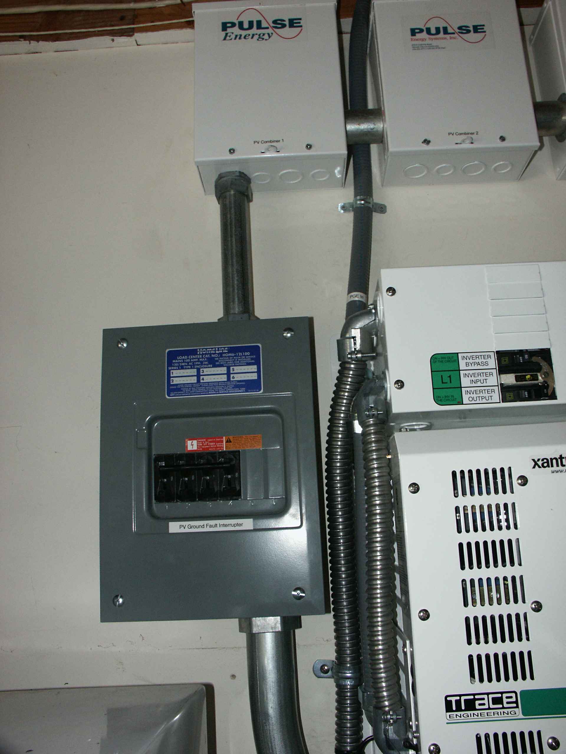
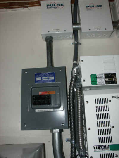
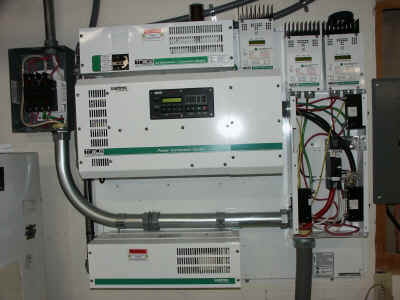
The gray box on the left is the PV Ground Fault Protector (PVGFP) the
three PV circuits go through it and over to the DC disconnect. At
the top of the picture you can see two of the combiners.
To the right of the PVGFP you can see the inverter (bottom) and the
bypass switch (top).
|
|
|
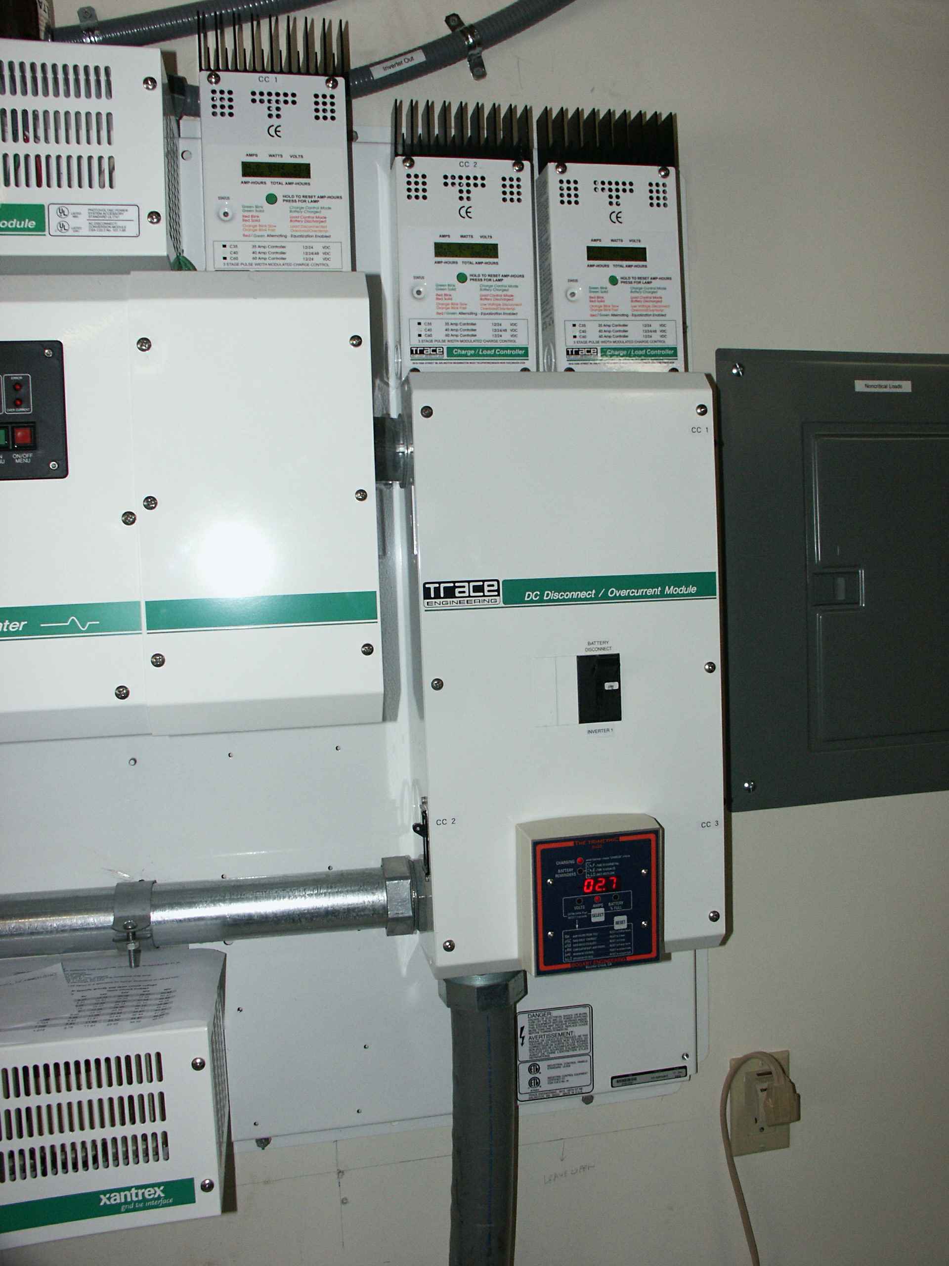
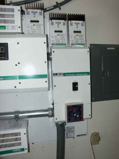
The box in the center is the DC disconnect. It contains three 60A
breakers, one for each PV circuit, a 250A battery breaker, and a Trimetric
battery monitor. Above it are the three charge controllers.
The PVGFP connects to the charge controllers through the 60 breakers and
then the charge controllers connect to the main DC bus. The
inverter's DC leads are connected to the bus and the batteries are
connected to the bus through the 250A breaker.
Visible on the left of the picture is the bypass switch (left),
inverter (middle) and GTI (bottom) and on the right of the picture you can
see the non-critical breaker panel.
|
|
|
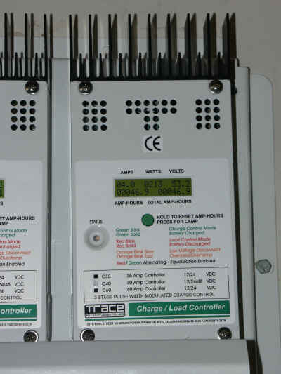
This is one of the charge controllers. On the top row of its display
you can see the volts and amps and watts the circuit is producing.
On the bottom row you can see the amp-hours and accumulated
amp-hours. This was an overcast day, so we are only making 213 Watts
on this circuit.
|
|
|
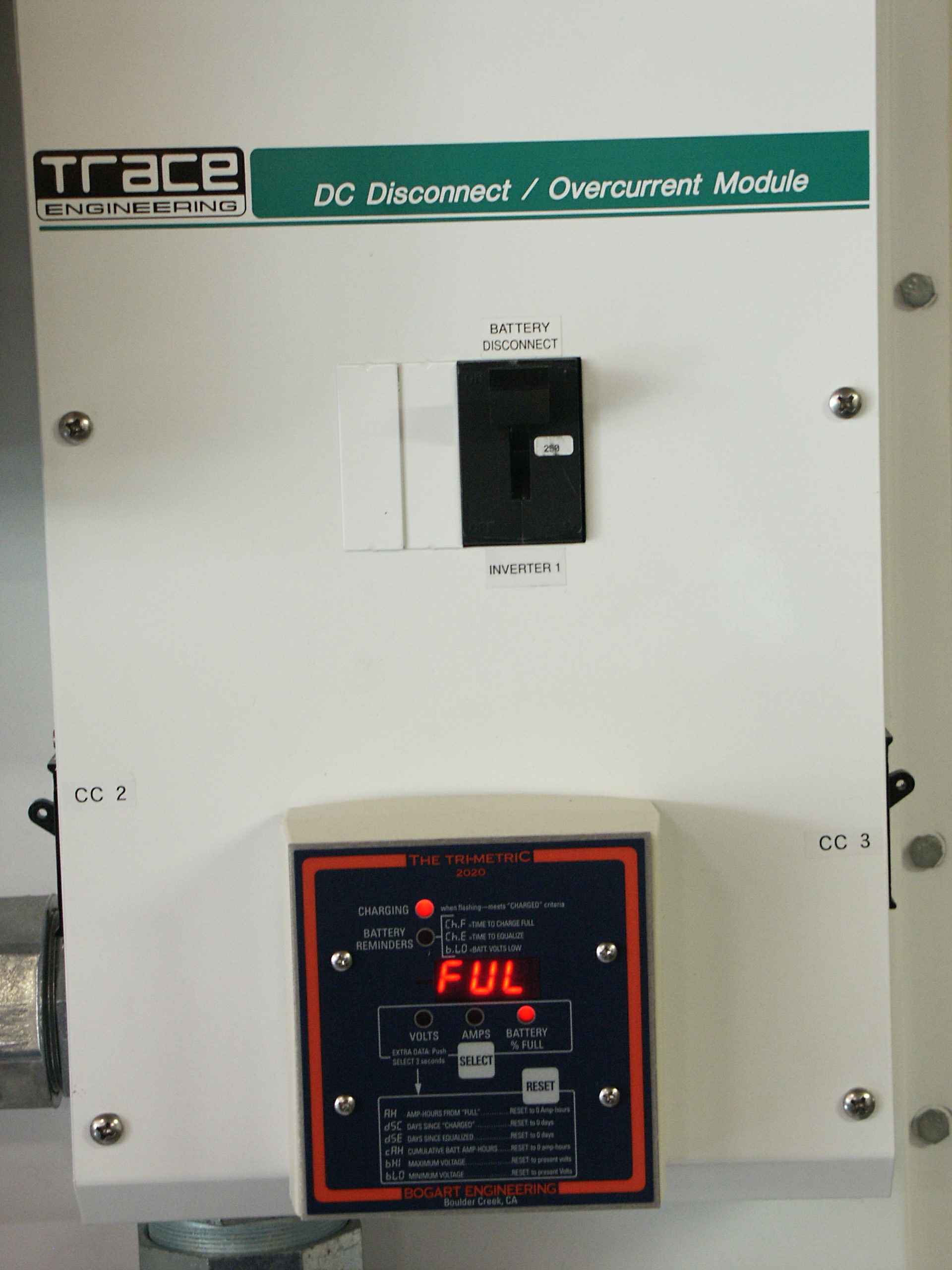
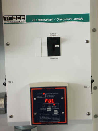
In this close up of the DC Disconnect you can see two of the charge
controller breakers, the battery breaker and the Trimetric battery
monitor. As you can see our batteries are fully charged.
|
|
|
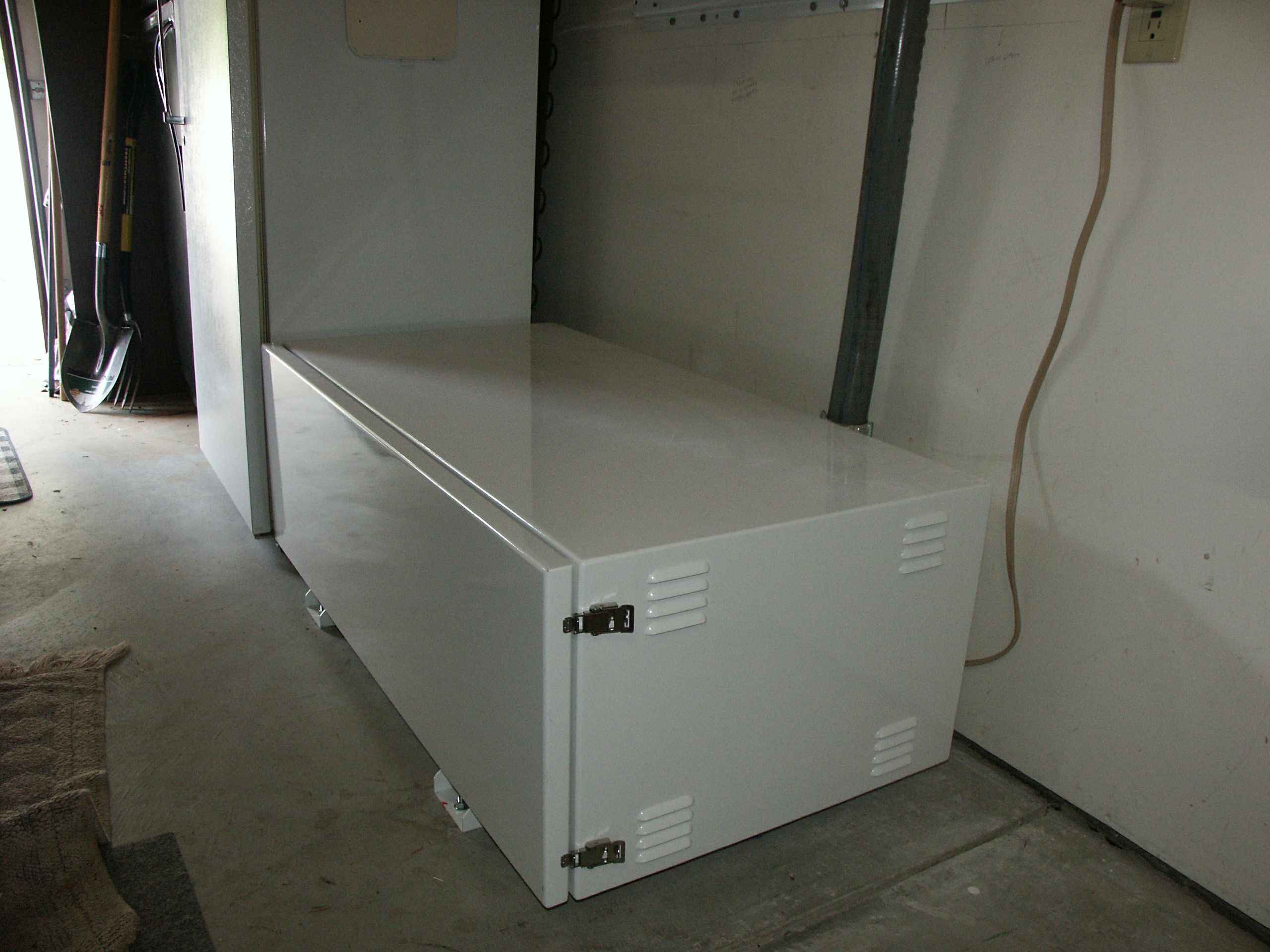
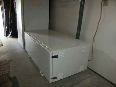
This is the battery box that contains the four Concorde batteries
connected in series to make 48 volts. The battery box is vented, but
the batteries are sealed AGM (Absorbent Glass Mat) type batteries that
don't make gas.
|
|
|
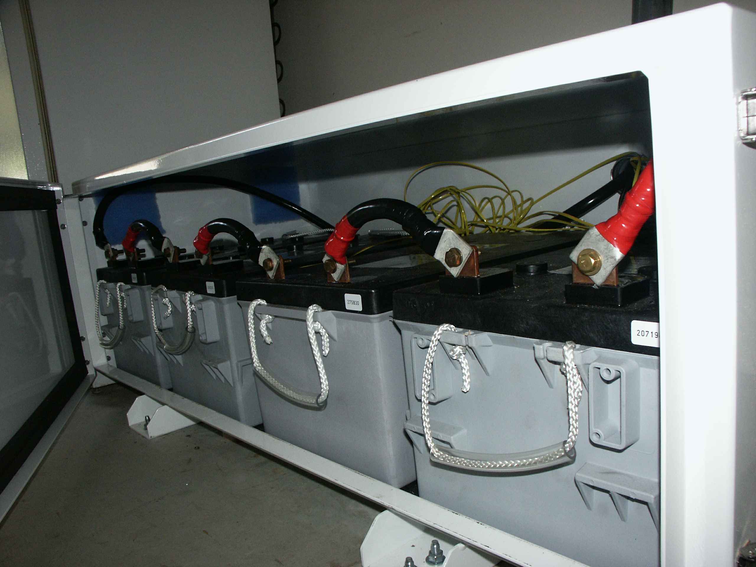
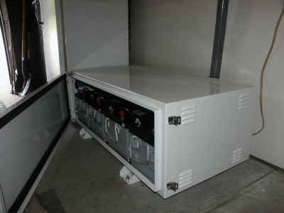
Here's the box opened up.
|

|
|
This is a close up of the batteries. The yellow wire is the excess
of the battery temperature probe wires. There are four battery
temperature probes. One for each of the three charge controllers and
one for the inverter. They use the battery's temperature to adjust
the charge current so that the battery is treated well.
|
 |
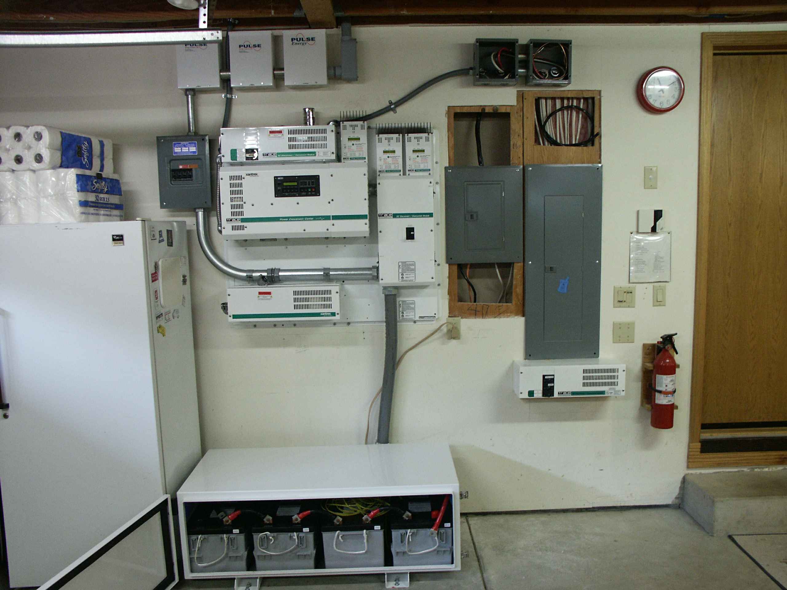
| This is what it looked like before I closed up the
walls after installing the non-critical breaker panel (the left one) and
rewiring the critical breaker panel.
|
 |
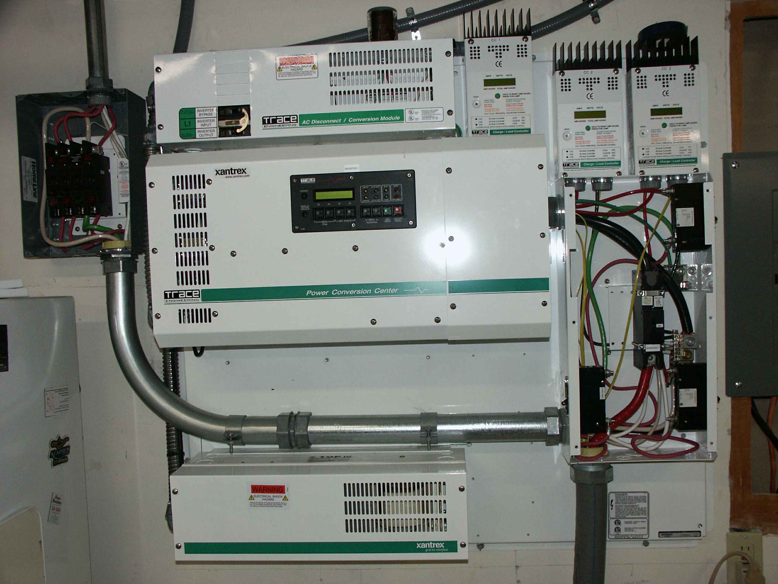
| This is what some of the things look like with their
covers off. |